Turning on the Sharpe Milling Machine
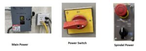
- There is a small electric power box on the back wall to the left of the machine, it supplies all the power to the machine. It is normally on, but it doesn’t hurt to check.
- On the right side of the machine about knee high is the main on/off power
- To turn on the rotor and bite use the on/off switch on the left side of the rotor.
- Turning the black knob clockwise moves ???? FOR (forward right to left if you face the milling machine). Counterclockwise to REV (Reverse left to right). OFF stops the rotor and will be the preferred way of stopping unless it is a real emergency.
- Setting up your Project
- You need to start with a piece of wood that has been squared up on the edge that you want to have parallel to the bed.
- To square up your project on the bed
- align the squared edge of stock with the edge of the bed.
- Lightly clamp the work to the bed (see clamping tools and Diagram at end of document).
- Check the alignment and tighten the clamps.
- A second way is to.
- Place two of the dowls, from the tool cabinet, that are the same size as the bed tracks.
- Then place your stock with the squared edged next to the dowls and clamp down.
- If your stock extends over the back edge of the bed check that the bit you intend to use can be moved far enough to make the cut perpendicular to the bed.
- If your distance between lengthwise cuts will be sufficient move the material out and by using a strip of wood for a space (make sure both edges are parallel) and place it next to the bed and align the squared stock with the edge of the spacer. Finish clamping your stock down.
Attaching the Bit.
- When selecting a bit be sure you know the diameter of the bit. Then select a collet for that size from the Tool Cabinet.
- The collet will be inserted vertically up into the chuck tapped end up and sticking out about an inch.
- There is a threaded shaft with a bolt head that will be screwed into the top of the collet.
- Once the collet is loosely secured insert the bit and hold it in place while you hand tighten top bolt snugly. The base of the collet should be roughly even with the bottom of the chuck.
- If everything looks in place finish tightening the collet bolt with the hex head end of the black hammer from the tool Cabinet. Be sure to remove the hammer and hang it back up in the tool cabinet.
- Hand turn the bit to be sure it will align along the axis of the rotor.
Setting the zero points for the X, Y and Z axis.
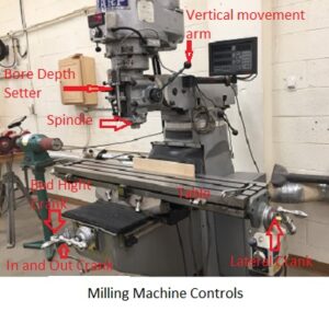
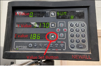
To use the electronic distance gauge uses X, Y, and Z coordinates. These are similar to the X, Y and Z axis on a graph. The X axis runs across the bed from the operator to the milling machine as he faces the machine. The Y axis runs parallel to the bed. The Z axis will be the depth of the cut. The zero X, Y, and Z points are the beginning of the cutting. You read the X, Y and Z values from top to bottom on the electronic distance gauge.
-
Zero the Z axis first. Move the cutting bit to the start of the first cut. Then lower the cutting bit to just touch the top of your material. Push the Value Set Button on the bottom to set the read out all zeros.
-
Turn on the rotor by turning the switch to FOR on the On/Off switch.
- If you want to cut at a depth of 1/8” slowly lower the cutter by turning until the Z value is 0.1250.
- Use the spindle lock on the right side of the rotor to make sure your read out stays at 0.1250. Now push the Value Set Button again to set the Z depth.
- Next you will cut the length of Y axis cut. First push the Value Set Button to set the Y zero point. Assuming that the bit is at the right end of the wood, with the Z depth still locked, turn the end crank counterclockwise to move the wood from left to right. Stop at the place you want to end the cut. If you have a specific length to cut you can read the middle, Y Value, until you reach the desired value. Now push the Value Set Button again to set the end Y value.
- Next you will cut the length of X axis cut. First push the Value Set Button to set the Z zero point. Turn the front, In/Out crank counterclockwise to pull the wood toward the operator. Stop at the place you want to end the cut. Now push the Value Set Button again to set the end X value. Make a note of the X and Y values. This will let you make a duplicate of your cut any time yon want. You now have a start point 0,0 and an opposite point for X and Y.
- Now you will cut the last Y axis length. Your Y length should be showing in the middle electronic distance gauge display. You will turn the end crank clockwise until that display becomes zero.
- Now do the same with the In/Out crank. Turn the In/Out crank clockwise until the top display value, X value, shows zero you will be back at the start or the 0,0 point.
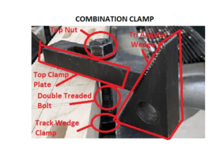
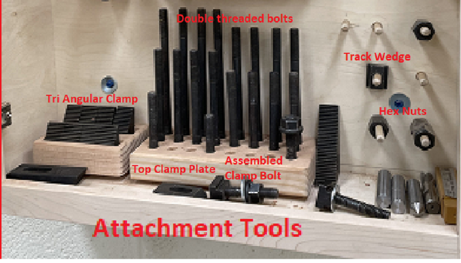
- First slide the Double threaded Bolt and Track Wedge into the Bed Track. The Double Threaded Bolt should not protrude beyond the bottom of the Track Wedge.
- Put the Clamp Plate onto the Double threaded Bolt and loosely attach the hex nut.
- Put the Clamp Plate on top of the stock.
- Insert the Tri Angular Clamp Block under the other end of the Clamp Plate and setting on the bed. Note the serrations to hold the Clamp Plate onto the Tri Angular Clamp Block
- The Clam Plate should tilt at a slight angle with the high end on the Tri Angular Clamp Block. The Clamp Plate should press on the top face of the stock not on the edge corner.
- Tighten the Hex nut. If the Clamp plate looks like it will dig into the stock, place a thin piece of wood to protect the stock.
- Be sure the Clamp Plates won’t interfere with the cutting bits.
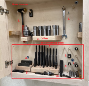
Milling Machine Tool Box